
I would like the help of some one of you to identify the pin configuration and the advice for some reading material relevant to understand how to manage this display. LED- Pick IO control back light off or PWM brightness controlīut i have no LED pin, instead i have a NC in place.I had take this pin analysis from Matthias from this forum In general, there are some tipical distribution as:īut i get this pin distribution on my display

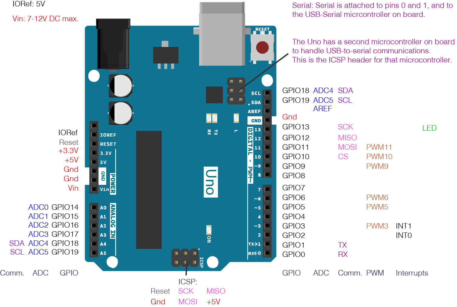
to one of the additional serial ports of the Arduino Mega, you can use jumper wires. But I cannot select input or output pin numbers greater than 13, which is okay for. In the previous post PS2 Controller Outline, the pin configuration. The pin configuration of the display does not match with any which i found in the web, can you help me with the identification? Instructions to set directions of the IO lines (not tested) pinMode (DPin, INPUT) pinMode (DPin, INPUTPULLUP) pinMode (DPin, OUTPUT) DDRX 0xnn // nn 00 - FF LH makes output LL makes input 2. I have configured my Simulink setup to run on Arduino Mega 2560 hardware. I newer in arduino and buy this item from ebay. All analog pins of this board can be used as digital I/O pins. Every pin of this board comes by a particular function which is allied with it. "1.8" Serial SPI TFT LCD Display Module ST7735B IC + PCB Adapter For Mega2560 R3" The pin configuration of this Arduino mega 2560 board is shown below. I'm have some struggles with the following device:


 0 kommentar(er)
